| In the basic transport version the Mi-2 helicopter had nine seats in the cabin, accomodating the pilot and eight passengers. The new helicopter had numerous modern features, and the mastering of its production put the production and technological capabilities of WSK Swidnik on a higher level.
The fuselage of the Mi-2 helicopter was an all-metal semimonocoque structure. In the joining of particular elements of the structure (frames, longerons, and skin) the modern techniques of metal-metal bonding and spot welding were extensively used. The front part of the main fuselage housed the cockpit, with pilot (port side) and passenger or instructor (starboard side) seats. The starboard side seat was somewhat set back with relation to the pilot seat. Apart from the seats, the controls and the instrument panel were also installed in the front part of the main fuselage. The nose structure, protruding in front of the cockpit, housed the battery bay and some elements of the electrical system.
On the port side of the cockpit there was an aft-sliding door for the pilot, with an emergency eject mechanism. Additionally, an optical icing indicator was installed on the door. On the starboard side there was a forward-opening hinged door which also had an emergency eject provision. The central part of the main fuselage housed the passenger cabin with six seats, some of them facing aft. In the rear part of the passenger cabin, on the port side, there was a large forward-hinged door. The door was protected from accidental opening by a special lock mechanism controlled from the pilot station. Additionally, should the door open in flight, there was a door-open light on the instrument panel. On each sides of the passenger cabin there were three windows, the rearmost one on the port side being the door window.
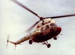 Early Mi-2
One of the very early, factory owned Mi-2 photographed in early 70s
Taken by: WSK PZL Swidnik
Early Mi-2
One of the very early, factory owned Mi-2 photographed in early 70s
Taken by: WSK PZL Swidnik
The ceiling plate of the central part of the main fuselage supported the engine mounts and the control system linkage brackets. Like the ceiling plate, the floor plate was a structural element, mounting the main landing gear shock absorber brackets. Below the floor there was a flexible fuel tank. The fuel tank compartment was protected from above by means of a sandwich plate made of two duralumin sheets separated with honeycomb filler.
The rear part of the fuselage was made of duralumin, as a variable section semimonocoque structure. It was made up of the tail boom and the final boom set at an angle of approximately 30o to the tail boom. The tail boom supported the tail rotor transmission shaft, and the cable linkage for tail rotor pitch and stabiliser control. Between the tail bom and the final boom there was the intermediate gearbox, transferring power to the tail rotor gearbox. The final boom, a riveted structure in the form of a truncated cone, joined the intermediate gearbox with the tail rotor gearbox. In the rear part of the tail boom a controllable horizontal stabiliser was installed, to improve the helicopter stability and longitudinal control, at various airspeeds. The stabiliser was coupled to the pitch-an-power lever.
The three-blade main rotor was made up of three blades, a fully articulated hub, and hydraulic lead-lag dampers. The rotor direction of rotation, looking from below, was anticlockwise. The blades had electrical deicing. As opposed to the SM-1, where the deicing system could operate for about 20 minutes, the deicing system on the Mi-2 had no operation time limitation.
The rectangular blades were all-metal. The primary structural element of the blade was the spar, equipped with an air pressure system for crack detection and warning. The spar was made of an alluminum alloy box profile. The inner and outer surfaces of the spar were shot peened for greater strength. The inboard end of the spar has a fitting for bolt attachment to the hub. On the front side of the spar the blade leading edge was installed, with heating elements of the electrical deicing system. On the rear side of the spar, twenty trailing sections were bonded. The trailing sections were made as aluminum sandwich structures with honeycomb filler. The blades had PVC paint coating for anticorrosive protection - black on the underside and blue-grey on the topside.
The blades were attached to the rotor hub via three hinges - lead-lag, flapping, and feathering. Blade movement in the lead-lag plane was damped by the lead-lag hydraulic dampers. The rotor hub was made of the rotor head, the intermediate yoke, feathering hinge pivots, hinge casings, swashplate, and blade pitch control levers. The three arms of the hub provided for blade attachment at 120o intervals. The hub arms had limiters of flapping movements of the blades.
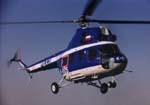 Mi-2 of Polish Police
 photographed in 90s
Taken by: WSK PZL Swidnik
Mi-2 of Polish Police
Mi-2 of Polish Police photographed in 90s
Taken by: WSK PZL Swidnik
The tail rotor was made up of the hub and two rectangular all-metal blades. The main structural element of the tail rotor blade was a spar machined from a one-piece forging. The tail rotor blades were also provided with heating elements of the electrical deicing system. The weight of the tail rotor assembly was 27.05 kg, and the weight of one blade - 3.99 kg.
The Mi-2 helicopter was powered by two GTD-350 turboshaft engines, each rated of 294 kW (400 KM). The engines were installed side by side, above the cabin, with the main transmission immediately behind them. The engines were manufactured at WSK PZL Rzeszów since 1966. The first units of the Mi-2 helicopter made at Swidnik had engines made in the Soviet Union, where a small number of the engines were originally manufactured. Power output of the engines was directed aft, and the exhaust was directed to the sides - left and right (the engines could be prepared for port or starboard side installation by repositioning the exhaust tubes). The compressor of the GTD-350 had seven axial stages and a centrifugal impeller. The maximum compression ratio was 5.9 at 45 000 r.p.m. The compressor casing and rotor were made of high-grade steel and provided with a bleed valve to prevent engine surge. The combustion chamber was reverse-flow type with a single, centrally mounted main burner. The ignition system was made up of a separate small burner and a semiconductor spark plug (igniter). The compressor turbine was single-stage. The free (power) turbine was two-stage and its maximum speed was 24 000 r.p.m. The compressor turbine wheel was air cooled. The exhaust section of the engine had two variable-section exhaust tubes, protruding outside through cowlings in the upper part of the helicopter fuselage. The engine had an individual lubrication system. Power generated by the free turbine was transferred onto the engine reduction gearbox, outputting rerduced r.p.m. onto an output shaft and then, via a splined coupling and a main drive shaft, to the main transmission. The engine fuel management system included a fuel control pump provided with a shutoff valve.
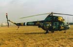 Polish Mi-2
Mi-2 from 103rd Ministry of Interrior Wing of Poland
Taken by: Milosz Rusiecki
Polish Mi-2
Mi-2 from 103rd Ministry of Interrior Wing of Poland
Taken by: Milosz Rusiecki
The main transmission, type designation WR-2, was supported on a duralumin support plate machined from a single-piece forging, installed on the ceiling plate aft of the engines. The transmission was a separate assembly, with a light alloy casing and gears of high-grade steel. The main transmission combined the power from the two engines and transferred the power onto the vertical main rotor shaft, the tail rotor transmission shaft, and the accessory drives. The accessories installed on the main transmission included the hydraulic block, AC generator, rotor speed tachogenerator, rotor brake, ignition coils for the engine ignition systems, oil temperature transmitter, and others. On the main drive shaft inputs to the main transmission, free-wheeling couplings were installed, to provide engine separation from the tramission on overrun. Another function of the free-wheel couplings was to permit individual engine startup, as well as declutching of an inoperative engine in case of one engine failure in flight. The reduction ratio of the main transmission (main drive shaft r.p.m. to rotor r.p.m.) was approximately 24. The weight of the complete main transmission was 290 kg. The main transmission had an individual lubrication and oil coolling system, and the air intake for the latter was located centrally, above engine air intakes.
The tail rotor transmission shaft was spported in six brackets with bearings, installed on top of the tail boom, under a special fairing. The intermediate gearbox, installed on the end of the tail boom, provided a 30o change in the direction of the tail rotor transmission. The intermediate gearbox was made up of one pair of bevel gears, and its dry weight was 12.4 kg. The tail rotor gearbox provided a 90-degree change in the direction of the transmitted r.p.m. to accommodate the tail rotor, and its dry weight was 17.0 kg.
The landing gear was made up of three assemblies - the nose leg and two main legs, plus the tail skid for tail rotor protection. The nose leg was a strut-cum-shock absorber (oleopneumatic), with a pair of twin wheels on semiaxles installed on a single forked trailing arm. The nose wheels had no braking, and a cam on the strut provided for self-aligning of the nose landing gear. Each main wheel was installed on a vee-shaped tubular arm with a strut-cum-shock absorber (also oleopneumatic). The main wheels had a compressed air braking system.
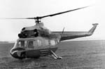 V-2 Prototype
One of the Soviet prototype of V-2 (Mi-2) helicopter
Taken by: OKB MiG
V-2 Prototype
One of the Soviet prototype of V-2 (Mi-2) helicopter
Taken by: OKB MiG
The helicopter had DC and AC (400 Hz) electrical systems.
The source of DC power were two starter-generators, 28.5V, 3 kW each. An auxiliary DC power source was provided by two 24V lead-acid or alkaline batteries which could also be used for engine startup in field conditions. AC power sources were three-phase generators (208 V nominal vltage, 16 kVA), a single-phase PO-250 or PO-500 converter (115 V nominal vltage, 250 VA or 500 VA), a three-phase PT-125C converter (36 V nominal voltage, 125 VA). |